Complex technical illustrations designed using CAD software require judiciously placed callouts, requiring precise tools from CAD software to achieve visual and mathematical consistency. For technical documentation for a more general audience, however, callouts are a necessary evil that occasionally ruin a beautifully rendered illustration, art, or drawing with misplaced lines and poorly positioned text references or captions.
There are no strict rules to placing arrows that point to a specific part - it really depends on the manual style, the subject, and the type of image. Vector images are the easiest because they can be broken apart for a "magnified view." Photographs are the least effective in technical documents because they don't fit very well when mixed with renderings and text. Bitmap images, such as screen captures, are all right as long as they were taken at a high resolution.
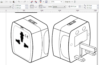
Technical writers are occasionally hard-pressed to find a good angle to point to that small button, control, or feature. Even more of a challenge is adjusting the text caption to fit an already cluttered page. Callouts aren't really that difficult to create in Adobe InDesign and Illustrator via a combination of the Pen tool, Line Tool, and Text tool. However, when you're working with an graphic intensive manual/document which requires more than half a dozen callouts (with labels) per screen capture and image, it can get very tiring. Although I spend more time with Adobe Creative Suite products than I do with CorelDraw X3, one of the tools I sorely miss in Adobe InDesign that CorelDraw has is the Callout Tool, which draws lines and inserts text.
To access the Callout Tool:
1. Open the Curve Flyout and click the Dimension Tool. For CorelDraw X5, there's a separate flyout for all Dimension Tools, including the 3-point Callout Tool.
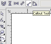
2. On the Property bar, click the Callout Tool.
3. Click once to set a start point and drag. Hold down the CTRL button to restrict the angle of the arrow. Press ESC to cancel the callout.
4. Click a second time to create a second line segment if needed. Double-click to end the callout and begin typing the text.
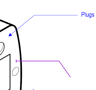
Like all vector objects, the created callout can be broken apart and edited as two objects: the text and the line segment. However, the callout properties can easily be changed without having to break apart the object. Text at the end of the callout can be selected using the Pick Tool, but much more useful is selecting the line segment to select the whole callout for editing color, thickness, and other properties.
To change the color of the text and callout, select the callout line segment and left-click a color swatch. To change the outline of the text and callout, right-click a color swatch.
To change the properties of the line segment only, open the Properties Dock by click Window, then Dockers. Select the Properties docker. On the Outline tab, change the width, color, and style of the line.
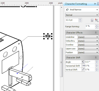
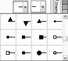
Often, callouts would have end markers to clearly identify what it is pointing to. CorelDraw saves users from having to draw separate boxes, arrows, and parallel lines and Group them with the line segment. On the Outline tab, select a Start arrowhead (or even an End arrowhead) to customize your callout.


0 comments:
Post a Comment